Myostat
Alpha-Bot Soup
T-Bot and H-Bot configurations can save space and increase performance.

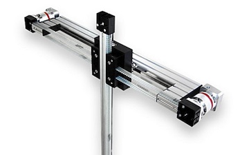
Traditionally, system designers looking to create multi axis XY or XZ systems purchase ball or lead screw actuators and bracketry combining the two actuators into a single system. T-Bot and H-Bot systems are available as ready-made, complete system alternatives that can save space and increase productivity.
T-Bot and H-Bot structures are examples of application specific designs that place more emphasis on model-based design and system integration. Used extensively in pick-and-place, sorting, gluing and inspection applications, these structures (named for the shape of their construction) are built around the belt drive components and employ two motors mounted to two pulleys driving one belt.
This is in contrast to standard XY configurations, which are constructed with two individual linear actuators where one actuator carries the other. In this standard configuration, the first actuator moves all the mass of the second actuator. In T-Bot and H-Bot configurations, the motors are stationery and, therefore, less mass is moved. Also, the space requirements are reduced as one axis can be minimized.
The resulting increase in performance, along with ease of manufacturing and the ability to fit into a smaller space envelope, make these structures attractive to machine builders; however, it’s important to note that motion control programming can be a challenge. When programming the machine, both position and timing must be addressed if accurate linear motion is required.
T-Bot and H-Bots work in a similar fashion to an Etch-A-Sketch. When the motors rotate at the same rate in the same direction, you have a linear motion along the X-axis. Moving the motors in opposing directions produces movement along the Y-axis. If one motor remains stationery and one motor is moving the motion will run 45 degrees across the XY plain.

X-Y orthogonal actuator configurations utilize standard Cartesian co-ordinates, which allows for each motor’s position to be easily mapped to the linear distance along the actuator or the axis of motion. T-Bot and H-Bots also move in the same physical Cartesian plain; however, the motor position coordinates are transformed as shown in the diagrams below.
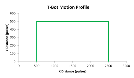
The motion profile of the T-Bot (Figure 1) illustrates the desired motion that we would like to achieve in real space. This profile has been chosen to represent a simple pick-and-place routine. The distance is representative of a linear move by a single motor, seen in pulses or steps.
When the two motors on a T-Bot move together, independently or alternate, a different motion is achieved. The equations that produce the required motion of the T-bot are seen below—X and Y representing the points on the desired T-Bot motion profile:
Motor 1 = -X +Y
Motor 2 = -X – Y
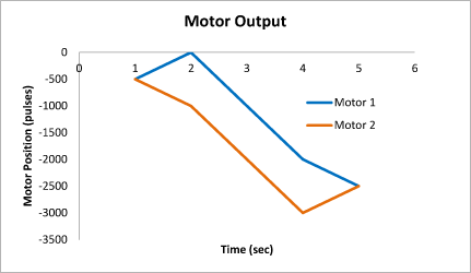
The moves that each individual motor must make to achieve the desired motion can be seen in Figure 2.

Here, the graph represents the distance each motor moves individually to achieve the rectangular move. This is based on equations
that relate back to the way the single belt of the T-Bot functions.
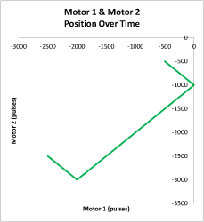
Accurate synchronization of the two motors is required to produce a linear move, with acceleration/deceleration rates and speeds matching to minimize any deviation from the linear move at the start and end of the move.Graph 3 represents the motion profile of the two motors working together.

The resulting motion profile is rotated 135 by degrees and offset from the
actual motion that the T-Bot accomplishes. Due to the way that the single
belt of the actuator functions, this movement of the motors produces the simple
pick-and-place routine commonly used in manufacturing industries.
With the wide variety of motion controllers available on the market, providing specific
guidance on the implementation for these systems is difficult. However, with an
understanding of the basic coordinate and speed transformations, engineers should
be able to implement one of these configurations and take advantage of the unique
mechanical advantages offered by T-Bot and H-Bot systems.
This article originally appeared in the November/December 2012 issue of Design Engineering
Alexa Loiskandl is a sales engineer for Myostat Motion Control Inc. with a B.Eng in Biomedical and Electrical Engineering.